/r/Optics


A place for questions and discussions pertaining to optical science and optical engineering.
Welcome to r/Optics
A place for questions and discussions pertaining to optical science and optical engineering.
Please do
- Be civil.
- Attach rough sketches with questions, when relevant.
Please don't
- Post about glasses, rifle scopes, or other common commercial optical devices unless it is related to their optical design.
- Excessively promote your own content.
- Directly advertise your own items.
Related subreddits
- r/binoculars
- r/telescopes
- r/glasses
- r/aimdownsights
- r/atoptics Atmospheric Optics
- r/fiberoptics
/r/Optics
18,827 Subscribers
Spatial light modulator Jenoptic
Hi,
I'm using a liquid crystal SLM from Jenoptik to act on some laser pulses but I'm running into some issue with the coding of this device.
Does anybody have some experience?
02:41 UTC
Phosphorescence spectrum
00:45 UTC


Nonlinear crystals for reducing the wavelength of sunlight to about 50 nm
Are there any inexpensive nonlinear crystals that can reduce the wavelength of sunlight to about 50 nm? This wavelength of 50 nm corresponds to a photon energy of approximately 25 eV, which is sufficient for ionizing atoms or photodissociating molecules.
Many nonlinear crystals used in the extreme ultraviolet range are costly and typically require lasers. However, the goal is to identify materials that could be affordable for individual use rather than large-scale research facilities.
Relevant considerations include:
- The crystal should be capable of generating wavelengths in the 50 nm range when pumped with sunlight or another accessible light source.
- It should be inexpensive for individual people or at least obtainable without specialized industrial suppliers.
Are there any nonlinear crystals that meet these criteria? If not, are there any nonlinear crystals that can reduce the wavelength of sunlight to about 100 nm? (Do not use profanity or blasphemy when commenting.)
17:36 UTC
IR-card recommendations for seeing femtosecond IR lasers (1300nm and 1700 nm)?
Hi, everyone! Could anyone recommend some IR-cards that can see femtosecond lasers with the wavelengths at 1300 and 1700 nm with a defined spot that doesn't fade away?
My client used Thorlabs VIS/NIR Detector Card: 400 to 640 nm and 800 to 1700 nm. The fluorescence usually fades away within a second, making the alignment extremely difficult. Thanks.
13:16 UTC
How do I calculate the distance for a custom FD mount speedbooster.
Greetings. I own a DSMC2 RED Weapon Dragon. I love using vintage Canon FD lenses and want to speed boost them down to the (slightly larger than) super35 sensor. I’m modeling the mount myself and having my buddy cnc it for me. I have a few questions for you smart people.
How far do I set the speedbooster from the sensor, or flange, or other point of reference?
Are all .71x speedbooster optics the same? Like is the optic in a .71x EF to RF speedbooster the same as a .71x Contax to Sony E speedbooster?
Where can I source just the optic, a good one.
Any other tips for me.
05:57 UTC
Diode Laser circular collimation via micro-optics
I want to collimate a single mode diode laser with 5 and 33 degree divergence in x, y axes. I have a tiny aspheric lens which can collimate. How to make it circular in micro optics level (like ~1 mm dimension)? I want to be low aberration as this beam will be at a later stage coupled to fiber after some processing.
04:35 UTC
As an Italian can I get into the US job market with an Italian degree?
hi, since I was 14 I was interested in Night Vision. after reading and doing some researches i’ve found that Politecnico of Milan offers a degree in physics engineering and a master in photonics and nano-optics, the master is entirely in english language.
do you think this could be a good route to get into this world or should I look something else?
10:14 UTC
I took some scintillator crystals to the dentist's office.
I brought several faceted scintillator lumogarnets to the dentist's office with me on my last checkup. My dentist is really cool and they let me take a video of the stones while irradiating them with the dental X-ray machine! The video is shot at 240fps, so we were able to catch the individual X-ray pulse events (since dental X-ray tubes don't have a 100% duty-cycle during operation). It's interesting to see both the garnets and the camera sensor react to the X-rays. The bright white dots that coincide with the crystals lighting up indicate an X-ray/CMOS camera sensor collision event, localized to only a few pixels around each individual collision site. The garnets from the top, going clockwise, are; Ce:YAG, GAGG, LuAG, and highly doped LuAG.
05:35 UTC
Anyone had any experience doing business with Novotech, Acton, MA?
If you've got good things to say, please post. If bad, please DM me.
I don't like publicly dragging anyone/thing through the mud.
Thanks, AoN.
00:05 UTC
Flat lens
Stupid question because i have literally 0 knowledge about this stuff. I got these glasses that have clip-on for outside wear. Now the lenses on the frames are completely flat, which i guess it’s because they don’t have any diopter on them. However i want to change the lenses to fit my own diopter, so my question is, can lenses with diopter be flat by any chance? I need to know if i need to specify something when i order the lenses, because if they are too curved the clip-on won’t clip as it should.
18:22 UTC
University of Arizona or UC Santa Barbara for a Masters with a focus in photonics?
I graduated with my BS in Electrical & Computer Engineering in 2022, and I've been working in the semiconductor industry since then. My job focuses on high-bandwidth semiconductors, and researching this led me to discover photonics. Even though I don't have a background in optics (besides the last half of a physics class in my undergrad where we covered geometric optics), I find it fascinating, so I've been looking for a masters program where I can study photonics and do research in it. Optical communication is another interest that's slightly tangent.
I've narrowed the colleges down to the University of Arizona and UC Santa Barbara (There might be other schools in the US, but I'm restricting myself to the southwestern US as much as possible to stay close to family).
UA has its own optics department with several photonics labs, so I would get a Masters in Optics if I went there. UCSB has its Quantum Photonics Lab and an Electrical Engineering Masters with a concentration in Electronics and Photonics.
Is one of these better for studying and doing research in photonics? It seems that studying at UA would expose me to a broader optics environment, and UCSB seems focused solely on photonics and its integration in electrical engineering. Is there anything that should push me to one of these colleges, or does it come down to personal preference?
23:43 UTC
Off Axis Parabola for Quasioptics Problem
Backstory: I'm doing research that involves focusing a beam of microwave energy in order to generate gaseous plasma. Due to problems that I won't go into detail about here, I need to come up with a creative solution to focus said microwave energy, and that has brought me to quasioptics, and more specifically an off-axis parabolic mirror.
I've attached a sketch of the setup that I'm interested in achieving. I will be launching 2.45 GHz microwave from either a horn antenna or a circular waveguide. I then am hoping to turn the beam 90° and focus it to a small spot size. The diameter of the collector (which is in fact a nozzle as this is for propulsion applications) is about 30 mm.
I am confined to a space 3 ft wide x 4 ft long.
However, not having a background in optics I am struggling a bit with figuring out how to design the OAP mirror. I understand that the parameters of interest in a regular parabolic reflector are its focus and aperture diameter, does that hold true for the OAP too? Does the distance from the beam source to the mirror matter as much as the distance from the OAP to the focus? What part of the parabola do you take the section from?
Any help, advice, or references would be greatly appreciated.
22:12 UTC
Square inside my lens
Hi guys! I'm new here. I just got a pair of eyeglasses from Zeelool yesterday nd at first I thought it looked okay and nothing wrong with it, but when I wore it, my eyes can't seem to focus properly, but I shrugged it off as maybe my eyes are still adjusting to it.
The next day, I went and defogged my lens using my breath to clean it with a soft tissue paper, but as I was about to wipe my lenses, I noticed a square inside the lens. Maybe a defect? Because I've never seen this in my previous pair before as well.
It's not a sticker because I tried cleaning it multiple times.
21:35 UTC
Specifications for a digital projector to be used with a reflective-style head-up display combiner?
Hello /r/optics, I'm working on a project designing a suitable projector to use with a holographic head-up display combiner, like this. https://i.redd.it/rslpz0yov2c81.jpg
I have found good information online, specifically here about how these devices work. This diagram is especially relevant. I'm hoping someone can help me answer a few questions about this subject. I know it's not a simple one.
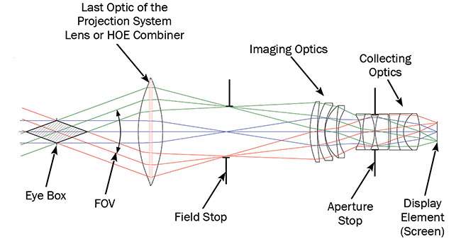
- Does the size of the image-producing screen affect the size of the eyebox where the collimated image is visible? I ask because digital projecters use very small LCDs or DLP chips, often 1/2" diagonal or smaller.
- Does the angle of the light reflecting off the last optic (the combiner glass) matter? Or does too great of an angle prevent the combiner from collimating the light? (assuming that the light is coming from beyond the focal point of the combiner)
Right now, I'm trying to learn as much as I can about this subject and expand my overall knowledge of optics, too, so any resources you can point me to are greatly appreciated.
Thanks very much
20:55 UTC
Optics Sanity Check: I am an optics noob and wanted to confirm that this system will relay an image to someone's eye afocally. I understand there are some spherical aberrations but just wanted to know if it was a somewhat viable design!
14:19 UTC
What Could this Mean?: A Weird convergence of rays in Code V
Hi! So, I used the optical ray tracing software code V to design this semester. I however, noticed the rays converging at some point even after the Intermediate image plain and the aperture stop which were both surfaces before this convergence. What do you think is the cause? I thought it was the lens so I removed the lens and it is still like that. Picture A is with the lens and Picture B is without the lens.
Note:
-It is not the aperture stop, as aperture stop is already set at surface 1 prior.
-it is also not the intermediate image plain as indicated in the picture.
Does anyone know why?
10:56 UTC
Collimator projecting distance
Hi,
I want to design for myself a collimator using parts from Thorlabs or Edmunds to collimate a test chart target for video camera but the trick is that I want to be able to simulate distance - for adjustable from 1m to infinity. Any ideas, advices and books are welcome.
Thank you
10:35 UTC
Noob Question regarding lens makers equation?
Trying to design a plano-convex lens with a thickness less than the radius. The equation is simplified with the second radius going to infinity, however I have not been able to determine where exactly the focal length is measured from? The front of the lens? The centre of the radius? Can’t be the back of the lens as thickness is arbitrary? Would be appreciated if someone could explain or send me to a good site with clear diagrams. Thanks
03:14 UTC
What iterative algorithm does Zemax use for Ray Aiming? (i.e how to find ray direction so ray will land at a specific stop coordinate)
Hello,
In Zemax, there is the concept of ray aiming. Meaning starting from a specific object location, we want to change the ray direction such that the ray hits the aperture stop at a specific location.
You can use geometric optics, and predict the location of the paraxial Entrance pupil. Aim the ray so that it hits the pupil. However, because of aberrations, the pupil is not a perfect image of the STOP so it won't hit the stop at the same location. Generally, that position is only a start guess to an iterative algorithm.
I was wondering if any one knows what the iterative algorithm is or how can you update the ray direction to it lands on a specific stop location with minimum compute?
One approach is to compute derivatives and update the ray direction based on that, but that's too time consuming and I doubt Zemax is doing that.
Thank you
02:55 UTC
How to simulate a point source with a given emission angle in Zemax
I am new to Zemax and want to do ray tracing for a point source radiating in a given emission angle placed some distance from a lens, and solve for zero marginal ray angle, as in the picture.
If anyone can write down what to input to the fields and to the lens data editor, that would be very helpful.
11:39 UTC
What Lies Beyond Our Own Planet with James Webb Space Telescope
02:59 UTC
IR Laser Projector Safety
Lens itself (left) and IR image of projection (right)
I have a question about the safety of the laser projectors, I am doing a project with a Realsense camera that will require it to be pointed at peoples faces, and I just want to understand the reasoning behind the Class 1 rating this projector has.
The Realsense D435 stereo camera has an IR projector that can be powered with between 0 - 360mW. The pattern projected is repeating, so I imagine the projector is quickly moving its projection over each section each frame. It seems like each pattern has about 60 points (see the image on the left of the lens itself). So 360mW / 60 points = 6mW per point... which is in the class 3 laser range, not class 1 (under 1 mW). I know I am missing something... just hoping to understand where I went wrong.
Second, I bought this Realsense used, and the Realsense manual says the IR projector can rise past Class 1 if alterations are made. Would it be reasonable to buy a power meter to measure the output to confirm no alterations have been made to the projector, or is it easy to see from the second image that each dot is <1mW (based on its intensity/glow or something)?
I know I might be being hyper safe here... just want to be sure I understand it before I start pointing it at people.
20:37 UTC
Lens / Source to Create Column of Light From Ceiling Tile Opening
Hi, I am working on an installation project where I'd like to create the impression of a very strong and focused beam of light appearing from an opening in a grid of ceiling tiles. The light source will be mounted above the level of the ceiling tiles and out of view. The outline of the beam should match the outline of the opening in the tiles so a square or rectangle. If viewed directly the light source should appear as a solid mass of light too bright to look at continuously.
I have done some experiments and determined that I can achieve the brightness I want by using a high power led array, but obviously this is not going to produce a focused beam.
I am wondering what kind of optic I can add to focus the beam for this light source, or if there is another type of source I should be using. I have seen some big fresnel lenses available with a square outline but not sure if that would be applicable here.
I have about 1-2 ft of space above the ceiling tile.
TYIA!
18:27 UTC
Achromatic lens
Hi guys. I'm working on measuring the OES of a light source and I plan to use a high-res spectrometer. So resolution roughly in the 10s of picometers and a wavelength spread no more than 10 nanometers (roughly at 350nm). Since I need to collect the light and focus onto the slit, can I get away with not using achromatic lenses for correcting chromatic aberrations and simply use standard fused silica singlet lenses? Thanks.
18:05 UTC
What happened with my telescope?
I took apart my 25x30 spyglass to clean it and decided to take the entire eyepiece apart, i didn't realize there was two lenses to the eyepiece, one thicker then the other? i did some research and apparently it's a kellner type eyepiece.
When i put it back together and looked through it, it looked really dreamy and werid, almost like the lens was really dirty even though it wasn't.
It turned out i had the thinner lens in the eyepiece the wrong way round and when i flipped it, it works perfectly fine now.
What happens to make a refractor telescope almost unusable if only one of the lenses is the wrong way round?
16:59 UTC
fiber optic simulation and analysis or experience
hello I am a student doing a project that would very important to getting accepted into my dream engineering school . for the subject I choose transmitting data with optical fiber , I would like to know what simulations , modelisations ,or analysis I can do to increase the quality of the content .or just any advise on how to go about explaining it from graphs , data or anything . and if it is possible to make some experiences that are not very complex. (at the undergraduate level )
16:30 UTC
Where to get dataset of speckle patterns?
I am working on a project combining machine-learning and optics. I am looking for a dataset of input pattern and speckle patterns produced by different diffusers. Any idea where can I acquire such dataset?
My guess is that these pairs are measured as part of imaging tasks, but never really released to the public. Any place to get/buy such datasets?
13:29 UTC
How are Diamond turned Diffractives toleranced?
I remember an old thread on tolerancing aspheres in this reddit - Couldn't find it to reference.
This is a related question seeking opinions/comments/ literature/ non-proprietary methodologies if they are shareable.
Diffractives are often utilized in thermal infrared optics, typically on Si and Ge substrates. How do you go about tolerancing these Diffractive features before fabricating them?
11:28 UTC